A geogrid roll can look simple beside a partly built wall. This page is the sequence, not a substitute for the approved drawing. Our what geogrid is article defines the mesh. Spacing, length, direction, connections, fill, and compaction all have to match that drawing. A manufacturer how-to that ranks nationally still cannot override the stamped plan for a San Diego permit wall.
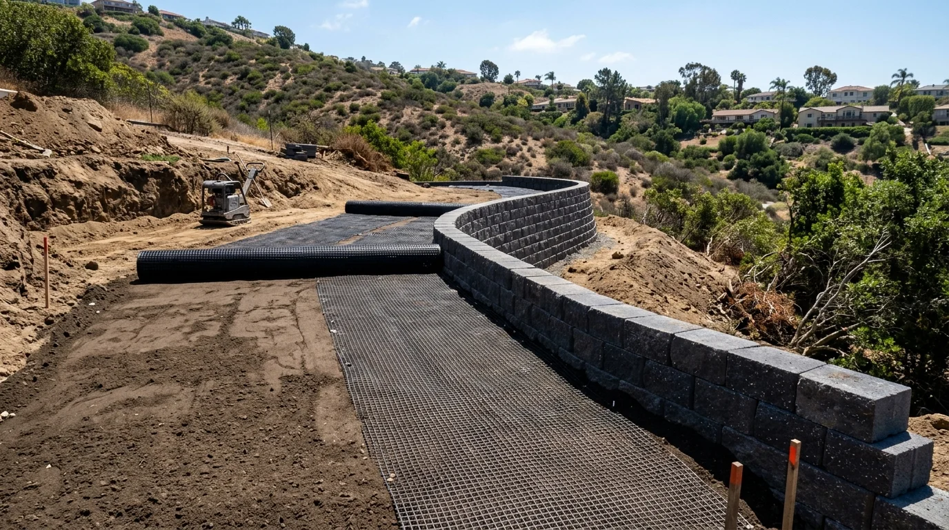
Geogrid works by turning soil into the structure
A reinforced wall isn’t just a row of blocks holding loose dirt. Its design treats the face, geogrid, and compacted backfill as a connected system. The grid extends from the wall into the reinforced soil zone shown on the plans.
That basic idea explains the installation order. The wall course reaches a specified elevation. The prepared backfill reaches that same stage. Geogrid is then placed in the position and direction shown by the design. The next soil lift covers it and receives the required compaction.
The exact details couldn’t be confirmed as one universal recipe. They change with the wall system, site, soil information, loads, and project design. Use the approved plans and the instructions for the selected product. Don’t copy dimensions from another property or a different roll.
This distinction matters across San Diego County. A hillside wall in East County may involve a different design problem than a level backyard wall near the coast. Parcel conditions also matter more than neighborhood assumptions. The City’s geologic maps are guides and don’t provide site-specific findings.
Geogrid often appears with segmental block walls, but the block brand doesn’t replace a project design. Read our geogrid reinforcement overview for more context on where reinforcement fits.
Before work starts, identify the controlling documents. These may include approved plans, engineering details, product instructions, and permit notes. If two details conflict, stop and get written direction from the project designer or building authority.
Layer spacing and embedment length come from the design, never the box
Geogrid spacing is the vertical location of each reinforced layer. Embedment length is how far that layer extends into the backfill. Neither value should come from leftover material, a neighboring wall, or a generic diagram.
Start by marking the grid elevations from the approved design. Match each elevation to the correct block course or construction stage. Then check the required length for that specific layer. Don’t assume every row uses the same length unless the plans show that arrangement.
Confirm the roll itself before cutting. The product name, grade, and roll direction should match the approved documents. A similar-looking grid isn’t automatically an approved substitute. Send proposed substitutions to the designer before installation.
The sequence should remain document-controlled:
- Confirm the wall course and grid elevation.
- Prepare the reinforced soil surface as the plans direct.
- Cut the specified grid product to the designed length.
- Place it in the direction shown by the design.
- Form the wall connection using the system detail.
- Hold the grid in its specified position during backfilling.
- Place and compact the next lift as directed.
Local permitting adds another checkpoint. Inside City of San Diego limits, a building permit is required when any trigger in Information Bulletin 220 applies. Triggers include surcharge loads and certain wall heights or backfill slopes. The height trigger is measured from the top of the footing to the wall’s highest point.
Those City rules don’t govern incorporated cities such as Chula Vista or El Cajon. They also differ from the unincorporated County rules. Confirm the property’s jurisdiction before relying on any permit guidance.
Rolling direction, tensioning and the mistakes that undo it
A geogrid roll has a designated placement direction. The project detail and product instructions must identify how that direction relates to the wall. Don’t decide orientation by appearance alone.
Lay each piece flat in the designed location. Use the specified connection at the wall face. Keep the grid aligned while the next backfill layer is placed. Any folds, damaged areas, unexpected gaps, or movement should be resolved before they disappear under soil.
Tensioning doesn’t mean inventing a pulling force. It means following the approved method for removing slack and holding the material in position. The correct method couldn’t be confirmed as universal because products and wall systems differ. Check the product instructions and project detail.
Several field shortcuts should trigger a pause:
- Turning a grid remnant sideways to make it reach.
- Shortening a layer because excavation space is limited.
- Adding an unapproved overlap or splice.
- Moving a designed elevation to another block course.
- Covering damaged material without written acceptance.
- Replacing the specified product based only on appearance.
Property boundaries can also affect the layout. The City’s standard retaining-wall bulletin says all wall elements must remain on the applicant’s property. It doesn’t allow encroachment onto neighboring property. Confirm boundaries before excavation and grid placement, especially on narrow side yards.
Walls tied to broader slope stabilization work need closer design coordination. Don’t treat added geogrid as a field fix for an unplanned slope, surcharge, or space problem. The designer needs to evaluate any change affecting the reinforced soil zone.
Compaction between layers is the step that gets skipped
Geogrid placement is only one part of each reinforced lift. The approved backfill and compaction instructions govern what happens above and around it. If that work changes, the completed wall no longer matches the documented sequence.
Build one controlled stage at a time. Confirm the facing alignment, backfill condition, grid elevation, grid length, and connection before covering the layer. Then place fill using the lift thickness and method stated in the project documents. Complete the specified compaction before advancing.
The correct soil type, moisture condition, equipment, testing, and compaction target couldn’t be confirmed as universal. Those details must come from the approved design, geotechnical recommendations, product instructions, or inspection requirements for that project. Don’t fill the gap with a number from a general article.
Drainage also needs to remain coordinated with reinforcement. The City of San Diego’s standard masonry design calls for drainage along the wall and prohibits discharge onto adjoining properties. Those specifications apply only to the City’s standard cantilevered masonry designs within their stated limits. They aren’t a universal geogrid detail.
For a segmental wall, follow the drainage design prepared for that system and site. Check where drain components cross or run beside reinforced layers. Don’t cut, shift, or omit geogrid to make an unplanned pipe fit.
Keep observations organized by lift. Record any product change, damaged section, inspection direction, or revised detail. Written answers are easier to follow than verbal field adjustments. They also give the next person a clear record before more soil hides the work.
How to tell from photos whether it was installed right
Photos can document visible installation steps. They can’t prove that a hidden wall matches its design. They also can’t confirm soil properties, compaction, or buried dimensions without supporting records.
Use photos as a layer-by-layer comparison tool. Start with a wide image showing the wall face, exposed grid, and reinforced backfill area. Take closer images of the product label, wall connection, grid direction, edges, and any designed overlaps or transitions.
Include a readable measuring reference where the design calls for a dimension. Photograph the full grid length before covering it. Capture the course or elevation marker that identifies the layer. Repeat the same views for every reinforced lift.
A useful photo set should let the designer or inspector answer these points:
- Was the specified grid product visible?
- Was the layer placed at the designed elevation?
- Did it extend in the required direction?
- Did its visible length match the plan?
- Was the wall connection formed as detailed?
- Were folds, damage, gaps, or field cuts present?
- Was the layer photographed before backfill concealed it?
Don’t judge quality from one finished-wall image. A straight face doesn’t reveal the buried reinforcement. Photos of exposed grid also don’t establish that later backfill work followed the required procedure.
Compare the images with the approved plans and product instructions. If something differs, send the photos to the project designer before continuing. Ask the local building authority which inspections and records apply to that permitted wall.
The City’s standard masonry designs have their own inspection stages, but those stages shouldn’t be treated as a geogrid inspection schedule. Confirm the correct process for the actual wall system. When hiring, verify the contractor through the CSLB Check A License tool.
When to call us
Call when the design involves geogrid, a slope, surcharge loads, uncertain soil conditions, or permit questions. The right local pro can review the project documents and coordinate required specialists.
Call us at (858) 400-4639 and we’ll connect you with a licensed local retaining wall contractor.